
USB (Universal Serial Bus) has become a ubiquitous interface in modern electronics, powering everything from keyboards to smartphones and external drives. But have you ever wondered what happens inside a USB cable or connector? In this blog, we’ll explore the USB pinout—what it is, how it works, and why it matters for your electronic projects.
What Is USB Pinout?
USB pinout refers to the arrangement of pins within a USB connector that are responsible for transferring data, power, and ground signals between devices. Each pin in a USB connector serves a specific function, and understanding how they work together is essential for ensuring that your USB devices function correctly.
USB Pinout Basics: What Each Pin Does
The pinout structure depends on the type of USB connector being used—USB-A, USB-B, USB-C, or Micro-USB. Let’s take a closer look at the most common USB connectors and their pinouts.
1. USB-A Pinout (Standard Type-A)
USB-A is the rectangular connector found on most computers, chargers, and peripheral devices. It is the most commonly recognized USB connector. A USB-A connector typically features four pins:
- Pin 1 (Vcc/5V): The 5V power supply used to charge devices or provide power to peripherals.
- Pin 2 (Data -): The negative side of the differential pair for data transmission.
- Pin 3 (Data +): The positive side of the differential pair for data transmission.
- Pin 4 (Ground): The ground pin, which completes the circuit and serves as a reference for all the signals.
2. USB-B Pinout (Standard Type-B)
USB-B connectors are typically found on printers, external drives, and some older devices. The pinout for USB-B is similar to USB-A but designed in a square-shaped housing:
- Pin 1 (Vcc): 5V power supply.
- Pin 2 (Data -): Negative data line.
- Pin 3 (Data +): Positive data line.
- Pin 4 (Ground): Ground pin.
USB-B connectors are used for devices that require a fixed connection, such as printers or external hard drives, and the pinout remains consistent across USB 2.0, 3.0, and 3.1 versions.
3. USB-C Pinout (Type-C)
USB-C is the new standard for modern electronics due to its compact, reversible design and higher data transfer speeds. USB-C can carry data, power, and video signals, and its pinout includes 24 pins in total. Unlike previous connectors, USB-C is symmetrical, so it can be plugged in either way. Key pins include:
- Pin 1, 2, 3, 4 (TX/RX Data Lines): These are high-speed differential data lines for transferring data between devices.
- Pin 9 (Vbus): This pin supplies power (typically 5V, but higher voltages for USB-PD).
- Pin 10 (GND): Ground pin, a reference for all signals.
- Additional Pins (for USB Power Delivery and Alternate Modes): These pins handle higher power levels and support additional functionalities, such as video output (DisplayPort) or audio.
One of the main benefits of USB-C is its ability to handle multiple functionalities over a single cable, including high-speed data transfer (USB 3.1 and beyond), power delivery (up to 100W), and video output.
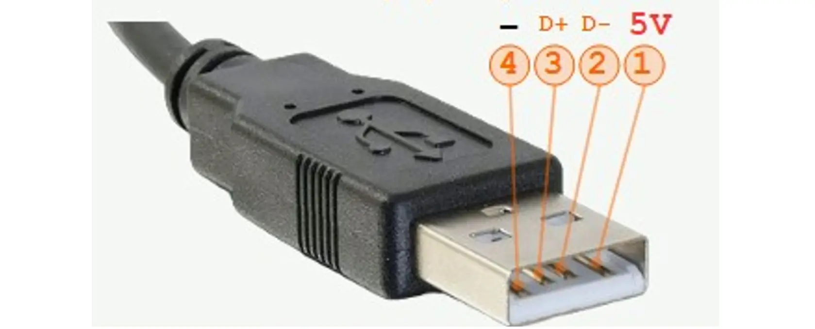
4. Micro-USB Pinout
Micro-USB connectors were widely used in smartphones, tablets, and other portable devices before the rise of USB-C. The micro-USB connector has five pins:
- Pin 1 (Vcc): 5V power supply for charging devices.
- Pin 2 (Data -): Negative data line for data transmission.
- Pin 3 (Data +): Positive data line for data transmission.
- Pin 4 (ID): This pin is used for identifying whether the device is acting as a host or a peripheral (e.g., in OTG mode).
- Pin 5 (Ground): Ground pin, providing the reference point for signals.
Micro-USB was popular because of its small size, but with the advent of USB-C, it has been largely phased out in favor of the more versatile and robust USB-C connector.
Why Is Understanding USB Pinout Important?
- Device Compatibility: Knowing the pinout allows you to create custom cables, connectors, or adapters that ensure devices will function as expected. Whether you’re working with a USB-A to USB-C cable or troubleshooting a USB connection, understanding the pinout ensures you connect the right signals.
- Power Management: USB is not just for data; it’s also used to supply power. If the power (Vcc) or ground pins are misconnected, it could prevent devices from charging or even cause electrical damage. In some cases, it can also prevent devices from communicating effectively.
- High-Speed Data Transfer: With newer standards like USB 3.0 and USB 3.1, faster data transfer rates are possible. Understanding how the data lines (Data +/Data -) work together can help you optimize your design for faster speeds, especially when working with USB-C, which supports transfer rates of up to 10 Gbps or higher.
- Troubleshooting: Whether you’re diagnosing an issue with your computer’s USB ports or working on a custom project, knowing the pinout can help you pinpoint problems like power failure, data loss, or faulty connections.
Conclusion
The USB pinout is the foundation of how data, power, and signals are transmitted between devices. Understanding the pinout for each USB connector type is critical for anyone working with USB technology. Whether you are designing devices, troubleshooting connections, or building custom cables, having a clear understanding of the USB pinout can make your work easier and more efficient. From the familiar USB-A connector to the new and versatile USB-C, knowing what each pin does helps ensure your projects run smoothly.
If you’re working on a USB-related project or just curious about how things work under the hood, take some time to get to know USB pinouts and their crucial role in today’s interconnected world.